Richards JSCS Series: Simplifying Medium-Voltage Cable Connections

May 15, 2026

Richards JSCS Series: Simplifying Medium-Voltage Cable Connections

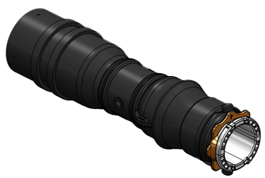
Reliable underground power distribution depends on cable connections that provide dependable electrical performance, environmental protection, and ease of installation. The Richards Manufacturing JSCS Series Cold Shrink Sleeve simplifies medium-voltage disconnectable joint installations by combining multiple components into one integrated design.

Designed for underground electrical distribution systems, the JSCS Series provides a fully shielded, submersible connection for applications through 35 kV.

What Is the Richards JSCS Series Cold Shrink Sleeve?

The Richards JSCS Series is a range-taking cold shrink sleeve designed for use with Richards' medium-voltage disconnectable joint system. It insulates and shields prepared cable connections while helping simplify installation in underground distribution equipment.

Made from Richards' cold shrink EPDM rubber, the JSCS features a durable, oil-resistant exterior designed for demanding underground environments.

Its integrated design eliminates the need for several separate components, including a cable adapter, retaining ring, vent rod, and separate jacket seal kit.

Key Benefits of the JSCS Series

  • Simplified installation: Combines multiple components into one integrated cold shrink sleeve.
  • Range-taking design: Accommodates a range of compatible cable sizes, reducing the need for additional adapters.
  • Durable EPDM construction: Provides a rugged, oil-resistant exterior for demanding underground applications.
  • Fully shielded and submersible: Designed for dependable performance in underground distribution environments.
  • Reduced installation effort: Features a short, non-spiral hold-out core designed for straightforward removal.
  • Existing system compatibility: Designed to work with existing Richards disconnectable joint interfaces, tools, and accessories.

Available Voltage Classes and Current Ratings

The JSCS Series is available in configurations for 15/25/28 kV and 35 kV applications, with 600 A and 900 A product options.

Richards lists the following continuous current ratings:

ConductorContinuous Current Rating
Aluminum600 A
Copper900 A

Catalog prefixes and application details from Richards' installation instructions:

Voltage ClassCatalog Prefixes
15/25/28 kVP625JSCS-, P925JSCS-
35 kVP635JSCS-, P935JSCS-
  • Housing sizes: O, P, and Q
  • Cable types: Jacketed concentric neutral (JCN), longitudinally corrugated neutral (LC), and tape shield neutral
  • Joint styles: I, Y, H, and U

Our online store carries the 15/25/28 kV JSCS Series sleeve in all three housing sizes: P625JSCS1O (Size O), P625JSCS1P (Size P), and P625JSCS1Q (Size Q).

The product family was designed and validated against applicable requirements of IEEE 386 for separable insulated connector systems, IEEE 404 for cable joints, and IEEE 592 for exposed semiconducting shields.

Always verify the specific product's ratings and compatibility before installation.

Where Is the JSCS Series Used?

The JSCS Series is designed for underground medium-voltage distribution systems where dependable, space-efficient cable connections are essential.

Typical applications include multiway cable splicing in underground distribution equipment, particularly in installations where space is limited and straightforward installation is important.

Its modular design supports flexible system configurations, while its integrated sealing and shielding features help reduce installation complexity.

How Do You Install the Richards JSCS Series?

The JSCS installs in a defined sequence: prepare each cable, attach the lug, park the sleeve, bolt the lug to the bus, seat the sleeve, remove the hold-out core, seal the cable jacket, and ground the joint. The steps below summarize the process from Richards' JSCS installation instructions (RP-II-93JSCS). They are an overview, not a replacement for the instructions packed with the kit.

Safety Requirements

  • The system must be de-energized during installation and any future operation of the product.
  • Do not touch or move energized connectors or components by hand.
  • Excess distortion of the assembled connector may cause failure.
  • Installation must be performed by trained personnel following normal and safe work procedures.
  • Do not nick or cut the cable insulation or the conductor strands during preparation.

What Is in the Kit?

Standard kits may include the following. Custom kits may vary, so check the contents for completeness, damage, and proper sizing before starting.

  • JSCS cold shrink sleeve body
  • Disconnectable joint (I, Y, H, or U style) and barrier bolt
  • Shear bolt lug or compression lug
  • Cable prep pack: grease, cable prep wipes, jacket mastic, sealing mastic, stress control mastic, and latex gloves

Richards also supplies a to-scale cable cutback template to use as a preparation aid. Some items, such as PVC tape, may not be included in the kit.

Step 1: Position the Cable and Expose the Metallic Shield

  1. Straighten and train the cable ends.
  2. Cut the cables so there is a 15 inch gap between them to allow for the bus.
  3. Clean the cable jacket up to 36 inches from the cable end.
  4. Remove the jacket and abrade the exposed area to the dimensions shown on the instruction sheet: 11 inches of exposed shield for strap or wire shielded cable, and 11 3/4 inches for metallic tape or LC shielded cable.

Step 2: Apply the Jacket Mastic (Strap and Wire Shielded Cable)

For strap or wire shielded cable, stretch one piece of jacket mastic and wrap it fully around the outer jacket with light tension at the position shown. For metallic tape or LC shielded cable, skip this step. The jacket mastic is applied later, in Step 10.2.

Step 3: Expose the Semi-Conductive Shield

  • Strap or wire shield: Fold the shields back, press them firmly into the jacket mastic, and secure them 3 inches back from the mastic with binding wire or a zip tie.
  • Metallic tape or LC shield: Wrap two layers of PVC tape to secure the metallic shield, then remove the metallic shield up to the tape (10 inches of semi-conductive shield exposed).

Step 4: Expose the Cable Insulation

Remove the semi-conductive shield to the dimension shown: 9 3/4 inches for strap or wire shielded cable, and 8 3/4 inches for metallic tape or LC shielded cable. Do not nick or cut the cable insulation.

Step 5: Expose the Conductor

Remove the cable insulation. Follow the instructions supplied with the lug for the insulation cutback dimension, which should not exceed 4 3/8 inches. Do not nick or cut the conductor strands. Confirm all dimensions against the cutback template, then repeat Steps 1 through 5 for the other cable.

Step 6: Install the Lug

  1. Clean the conductor of debris. For aluminum conductor, wire brush it and insert the lug immediately, sliding it until the conductor is fully seated in the barrel.
  2. Rotate the lug so the spade is parallel to the contact face of the bus.
  3. For shear bolt connectors, install the lug using the separate instructions supplied with it. For crimp connectors, select the correct tool and die from the crimp chart, start the first crimp just below the knurl line next to the pad, and make at least the minimum number of crimps indicated.
  4. Carefully wipe any excess inhibitor from the lug and cable insulation.

Step 7: Check the Lug

Confirm the distance from the end of the lug to the insulation cutback does not exceed 7 1/8 inches.

Step 8: Apply the Stress Control Mastic

Clean the insulation with the approved wipes, wiping from the lug toward the shielding. For metallic tape or LC shielded cable, remove the PVC tape from Step 3 first. Apply the stress control mastic centered over the edge of the semi-conductive shield cutback, with light tension so it stretches slightly and completely wraps the cable.

Step 9: Grease, Park, and Install the Sleeve

  1. Apply grease: Coat the exposed cable insulation and stress control mastic with the supplied or approved silicone grease.
  2. Park the sleeve: Slide the sleeve body over the cable so the hole in the lug is visible.
  3. Bolt the lug to the bus: Stack the belleville washer and flat washer on the bolt, insert the bolt through the lug, and hand-tighten it so all cables fit on the bus. Tighten until the top shear bolt head shears off.
  4. Seat the sleeve: Clean the joint interface, grease the bus interface with approved silicone grease, then slide the sleeve body over the lug and push it onto the bus. This can be done by hand or with the optional P6JAT1 or P6JAT3 installation and removal tool.
  5. Add restraints or clamps: If using sleeve restraints, seat them in the sleeve housing channels (I joint: one JRI; Y joint: one JRI and one JRE; H joint: two JRI; U joint: two JRE) and tighten until the screw clicks. At 35 kV, if restraints are not installed, interface clamps must be installed on each sleeve and tightened the same way. Sleeves must be fully seated before restraints can be installed.

Repeat the lug and sleeve steps for the other cable.

Step 10: Remove the Hold-Out Core and Prepare the Shield

  1. Push the removal ring against the core flange and twist so the cutting teeth break the tape on both sides. Remove the core from the rubber housing by hand, or use the P6AT-CS2 core removal tool. Do not twist the core while removing it.
  2. Separate the core into two halves and clip any plastic rings left on the cable.
  3. For metallic tape or LC shielded cable, install jacket mastic aligned with the jacket cutback, wrap tinned copper braid around the exposed metallic shield, secure the braid 3 inches back with a zip tie or binding wire, wrap the constant force spring over the braid, tighten it, and secure it with two layers of PVC tape. Then press the solder block into the jacket mastic. Strap or wire shielded cable skips this step.

Step 11: Apply the Sealing Mastic

Apply the sealing mastic so it overlaps the stress control mastic and completely covers the jacket mastic. Compress it to form a smooth transition to the stress control mastic, which helps during jacket seal application.

Step 12: Apply the Jacket Seal

Grease the area shown using only the supplied or approved grease. Hold both pull tabs and pull outward so the jacket seal completely covers the sealing mastic, making sure the mastic is not dislodged as the seal unfolds. Repeat Steps 10 through 12 for the other cable.

Step 13: Ground the Joint

Each component (sleeve, bus, and sleeve restraints) has one or more ground eyes, and all must be properly grounded.

  1. Install bleeder wire (#14 AWG or larger) through the ground eye of each component. When sleeve restraints are used, the connection through the bus and sleeve ground eye is optional. Twist for a snug connection without damaging or tearing the ground eye.
  2. Connect the bleeder wires to the shield wires, or to the copper braid on metallic tape or LC shielded cable.
  3. Ground the cable shield according to approved practice.

For full dimensions, illustrations, and any variations in equipment or procedure, refer to the complete instruction sheet supplied with the product or available from Richards Manufacturing.

Why Choose Richards JSCS Cold Shrink Sleeves?

For utilities and electrical contractors, reducing installation steps without compromising system requirements can improve efficiency in the field.

The Richards JSCS Series combines insulation, shielding, and jacket sealing into one range-taking cold shrink sleeve. By eliminating several separate components, it offers a practical solution for medium-voltage disconnectable joint installations.

For underground distribution projects requiring a compact, fully shielded joint system, the JSCS Series is worth considering.

Need help selecting the right JSCS Series product? Contact Powertech Associates for assistance identifying the appropriate voltage class, current rating, and compatible joint configuration. Sizes O, P, and Q are available in our online store.

Explore the Richards JSCS Series Cold Shrink Sleeve for product details and technical documentation.

Interested in this product?

Contact us, request a quote, or order online.